Business
Development of next-generation switched reluctance motor
History of switched reluctance motor(SRM)
The world’s first switched reluctance motor
R. Davidson (UK) made an electric locomotive driven by SRM. Test run on the Falkirk Railroad.
P.G.Froment(France) made SRM for printing press
Page ran a locomotive at 30km/h on the Baltimore and Ohio Railroad with a 16hp SR motor.
S.A.Nasar proposed the name Switched Reluctance Motor.
Started full-scale development and started to be used in products (variable speed operation by inverter)
Current status of switched reluctance motor
With the rapid shift to electric vehicles, permanent magnet synchronous motors are expected to face challenges in the future, such as the cost of permanent magnets and the stable supply of rare earths. As an alternative motor to permanent magnet synchronous motor, switched reluctance motor has a simple structure and high output density. However, at present, it is difficult to use switched reluctance motors for traction motors because of the following issue.
Inverter cost increase
Compared to conventional 3-phase inverter, more diodes are required and the wiring capacity is large due to the low power factor.
Noise and vibration
Due to its structure, torque ripple is larger than that of a permanent magnet motor.
Development of next-generation switched reluctance motor
With the rapid shift to electric vehicles, permanent magnet synchronous motors are expected to face challenges in the future, such as the cost of permanent magnets and the stable supply of rare earths. As an alternative motor to permanent magnet synchronous motor, switched reluctance motor has a simple structure and high output density. However, at present, it is difficult to use switched reluctance motors for traction motors because of the following issue.
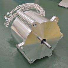
12/10type hex connection SRM
The new SRM has a centrally wound 6-phase coil in stator A-F phase, with two coils of the same phase in parallel. The beginning/end of the winding of each layer coil is connected to the coils of the two adjacent phases, and we call this “hex connection" because the wiring takes the shape of a hexagon.
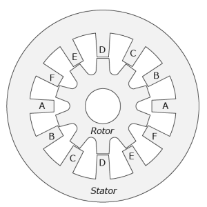
Fig. 1. Cross-sectional view of 6-phase 12/10type SRM
Connection of a conventional 6-phase inverter
Fig. 2 shows the drive circuit of a conventional 6-phase inverter. The 6-phase inverter consists of 6 bridges, and each bridge has a total of 12 switching elements in the upper and lower stages. Due to the large number of switching elements used, the high cost of the inverter has been an issue.
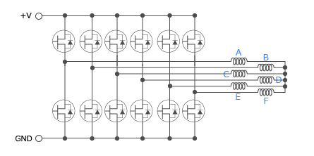
Fig. 2. Conventional 6-phase inverter
Connection with 9-switch Inverter
This is why the 9-switch inverter shown in Fig. 3 was developed. Each of the three bridges has three switching devices connected in series. This allows the number of switching elements to be reduced from 12 to 9.
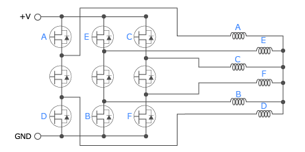
Fig. 3. 9-switch inverter
Connecting a 9-switch inverter with a hex connection
Furthermore, compared to the conventional star connection, the use of hex connection as shown in Fig. 4 reduces the torque ripple and increases the torque density, and the combination of 9-switch inverter and hex connection results in a SRM with better operating characteristics than before.
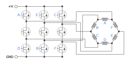
Fig. 4. 9-switch inverter and hex connection
Connection with improved 9-switch inverter
The switching pattern when using the circuit in Fig. 4 to drive a 12/10type SRM with pulsed voltage is
– Right column switch ON / Middle column switch OFF / Left column switch OFF
– Right column switch OFF/Middle column switch OFF/Left column switch ON
Middle column switch are always open.
Therefore, as shown in Fig. 5, in the improved 9-switch inverter, all the switching elements in the middle row are replaced with diodes, enabling cost and size reduction while maintaining equivalent performance.
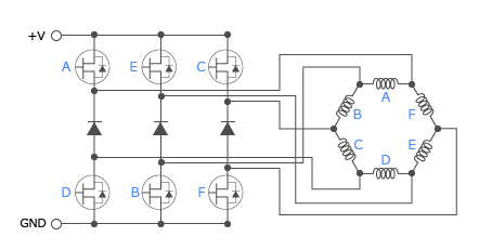
Fig. 5. Improved 9-switch inverter and hex connection
Improvements
Prospects for next-generation switched reluctance motor
Development of current superimposition variable magnetic flux reluctance motor
Proposal for hex connection
Realization of control by improved 9-switch inverter and hex connection
To the next-generation SRM
